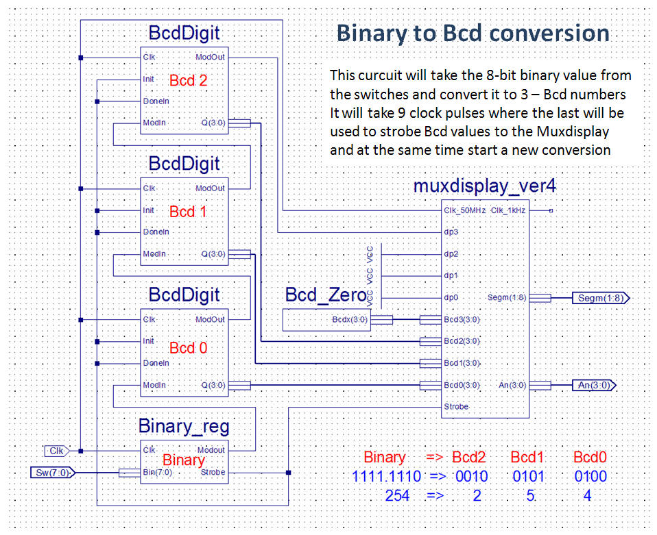
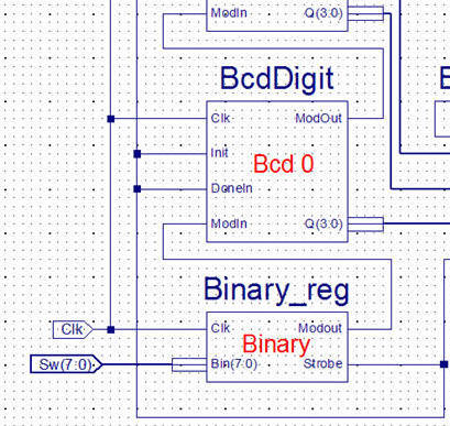
[Home] [Dice] [BCD to 7 Segm] [Mux Display] [Bcd Counter] [Toggle Button] [StopWatch] [Conversions] [RPN Calculator] [The Gnome II] [74x382 ALU (8-bit)]
Conversions
Up ]


The natural number for a digital system binary, how ever can it be necessary to use BCD numbers (with radix 10) in order to present data at displays etc.

Design a digital system which demonstrates the principles found here - your free to arrange the different components which can form a solution.


BcdDigit

This "slightly modified" shift register will accept a binary input at Modin and deliver the Carry bit from a Bcd number at the Modout. The Q output will present the value of the Bcd shiftregister - how ever will it only be correct after the required number of clock pulses.

When Init=1 will the Bcd shift register be initialized (set to "0000") and the shift register will only shift when Donein = 0

You can find the code for this component here - but try to write your own.

Binary_reg

This component consist of two processes (at least in my solution)

1) a process  which implements a counter with the sequence 0,1,2,3,4,5,6,7,8.
The numbers 0 to 7 indicates that the conversion running where as number = 8 indicates that the conversion ended (hence will Strobe = 1 for one clockcycle)

2) a process which implements a "normal" shift register.
The shift register loaded with the Bin(7:0) each time the counter value = 8
For counter values 0 to 7 will the shift register shift one bit left - the leftmost bit will always be found at the Modout


Bcd_Zero

Actually only a 4-bit 0 like "0000"


Muxdisplay_ver4

Pretty much the same as Muxdisplay_ver3 but with the differences:

1)  The Bcd inputs now 4x4-bit instead of 16-bit vector
2) The dp now 4 single signals instead of one 4-bit vector
3) The most important difference - The input at Bcd3, Bcd2, Bcd1Bcd0 and the dpx
signals will only be visible at the display with a rising edge at Strobe.